Exoskeleton Arm controlled by sEMG signals and Joystick Device

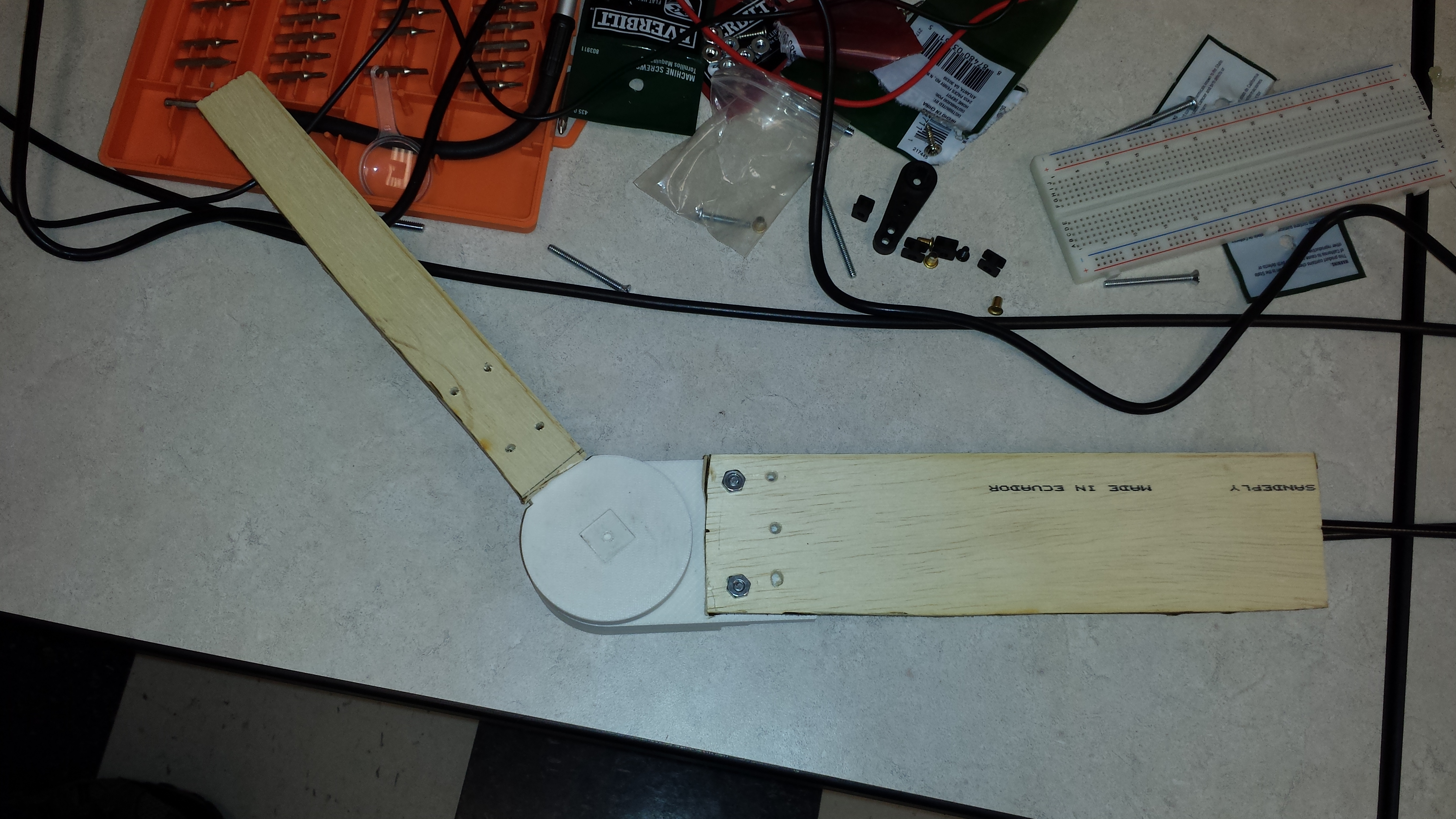
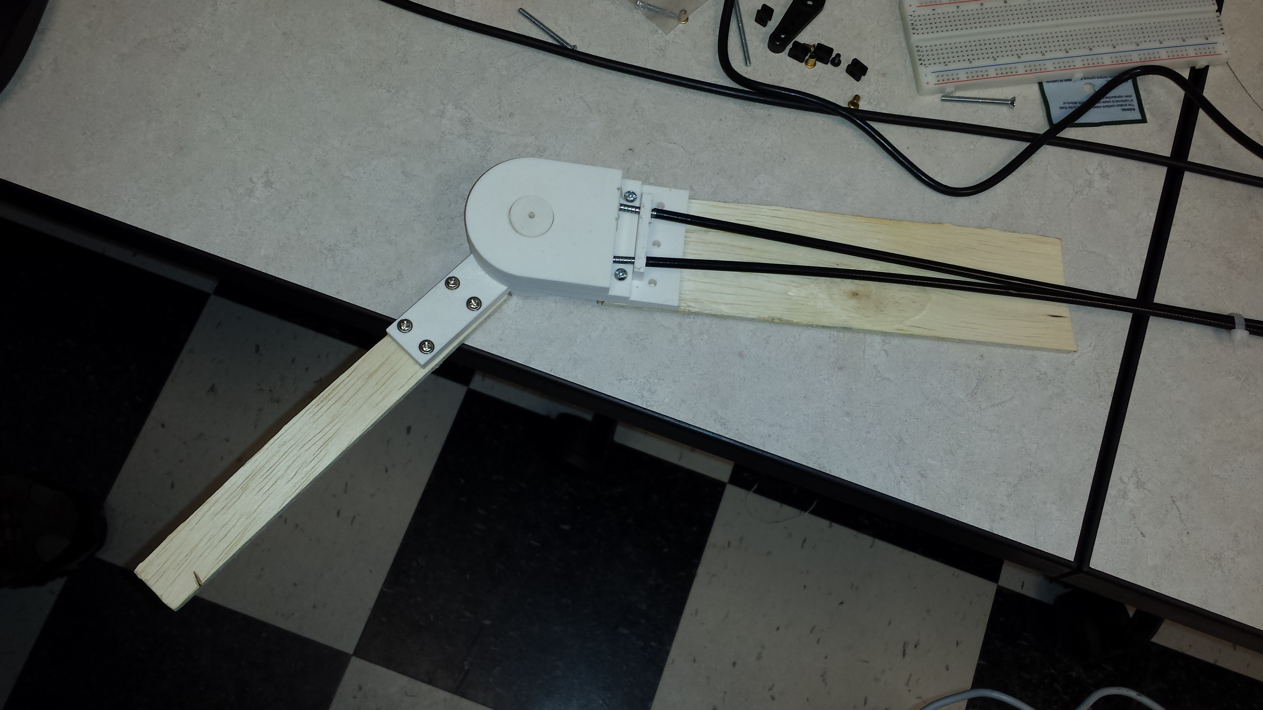
In the video above, through 3D printed parts, we were able to construct an exoskeleton prototype that was successfully able to move through the sEMG signals located on the bicep and tricep. The servo used to control the prototype exoskeleton is shown in this link.

The actual sEMG signals from the video are shown in the graphs below.

Download – sEMG w/ Exoskeleton Graph

As shown in the video above, when there was a bicep or tricep movement, the exoskeleton’s joint would move in opposite directions.

In our design project, we are aiming to also use an emergency joystick device to control the exoskeleton. The reason for this, is that in an emergency situation where the sEMG signals are not processing as expected, the joystick device can prevent hazardous outcomes.

The maximum current that the servo had drawn was slightly lower than 9 Amps. Through this knowledge, a suitable battery is going to be ordered to meet this specification, as well as at a cost of lower than 50 dollars. In the ideal situation, the battery must able to handle the maximum current for a minimum of 1 hour.

After testing the exoskeleton with sEMG signals and the joystick device, we then tried to actually use the exoskeleton with an arm.

20140223_152929

20140223_152920

20140223_153516

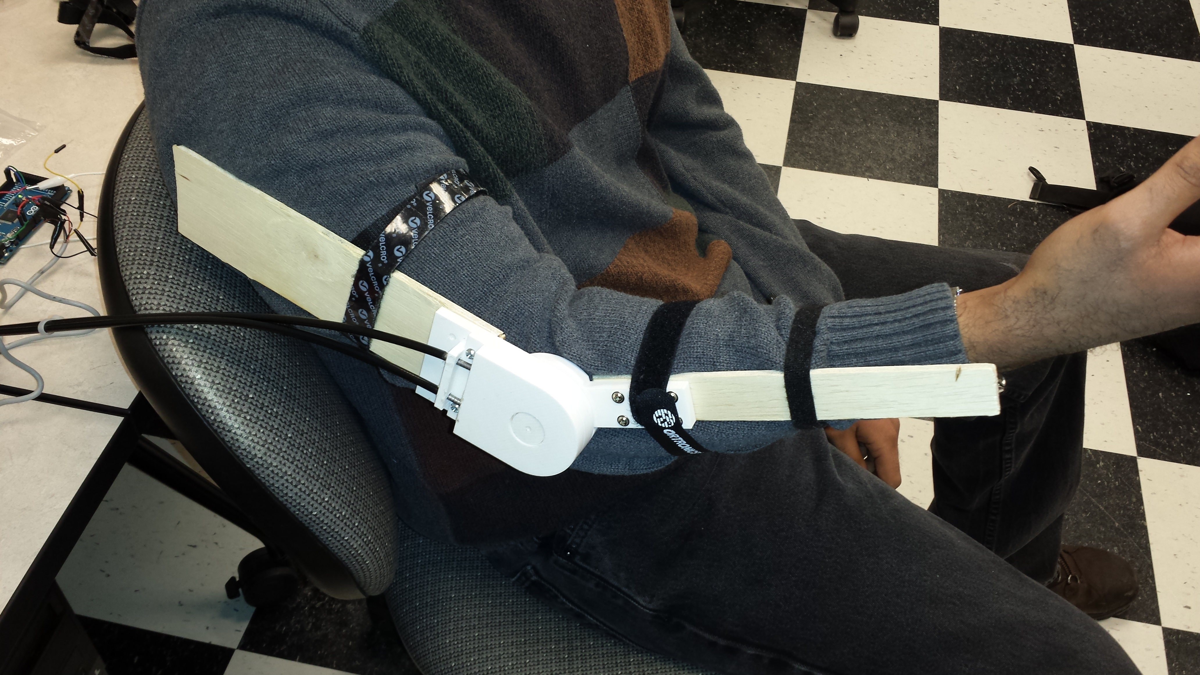
The Velcro straps were used to hold exoskeleton prototype with the arm. However, after performing this test, the arm barely had any movement, the design needs to be changed in a way that the servo is able to exert maximum torque to the arm.

Progress Report #1

This is our most up-to-date progress report.

Download – Progress Report #1

Video of the bicep and tricep controlling the rotation of a servo

Materials

  • sEMG Circuit x 2 (Bicep and Tricep Inputs)
  • sEMGs + alligator cords
  • Continuous Servo Motor
  • Arduino Mega2560
  • Serial Connection with the Computer (Arduino IDE + MATLAB)
  • Power Supplies (+9V, -9V, +5V)

A serial data connection was established between MATLAB and the Arduino Mega2560 in order to record data into graphs. The data recorded into MATLAB was real-time, meaning, the graphs were recording the data points immediately after the sample was taken. The method used to determine which direction the servo rotates was determined by a Threshold Method.

The threshold method is described in code below:

  //diff_voltage = bicep_voltage - tricep_voltage
  //Move up
  if (diff_voltage > 0.3){
    myservo.write(75);
  }
  //Move down
  else if (diff_voltage < -0.3){
    myservo.write(120);
  }
  //Rest
  else {
    myservo.write(95);
  }
  delay(500);

This method looks at what point on the graph the difference voltage (bicep – tricep) is and sends a signal to the servo indicating the direction of movement.

The graphs shown below, show the bicep, tricep, and the difference between the bicep and the tricep.

Download – EMG Signal Graphs

From looking at the “Bicep – Tricep” graph, when the user is flexing his or her arm, the voltages are generally more positive. However, when the user is straightening his or her arm, the voltages are generally more negative. At rest, the user has a voltage difference closer to zero. Since, there is a noticeable ripple voltage, there are some small inconsistencies with how the servo moves. In order to handle this issue, we took the RMS (root-mean-square) of a certain range of values through our analysis.

The graphs shown below, show the different RMS graphs based on the original “Bicep – Tricep” graph. For example, the RMS10 graph represents for every 10 values an RMS value is taken.

Download – RMS Graphs

The graphs below show the servo moving graphs. Where +1 is when the arm is being flexed, -1 is when the arm is being straightened, and 0 is when the arm is at rest.

Download – Servo Moving Graphs

One can conclude from the graphs that the RMS values would theoretically have better consistency with moving the servo.