
In the video above, through 3D printed parts, we were able to construct an exoskeleton prototype that was successfully able to move through the sEMG signals located on the bicep and tricep. The servo used to control the prototype exoskeleton is shown in this link.
The actual sEMG signals from the video are shown in the graphs below.
Download – sEMG w/ Exoskeleton Graph
As shown in the video above, when there was a bicep or tricep movement, the exoskeleton’s joint would move in opposite directions.
In our design project, we are aiming to also use an emergency joystick device to control the exoskeleton. The reason for this, is that in an emergency situation where the sEMG signals are not processing as expected, the joystick device can prevent hazardous outcomes.
The maximum current that the servo had drawn was slightly lower than 9 Amps. Through this knowledge, a suitable battery is going to be ordered to meet this specification, as well as at a cost of lower than 50 dollars. In the ideal situation, the battery must able to handle the maximum current for a minimum of 1 hour.
After testing the exoskeleton with sEMG signals and the joystick device, we then tried to actually use the exoskeleton with an arm.
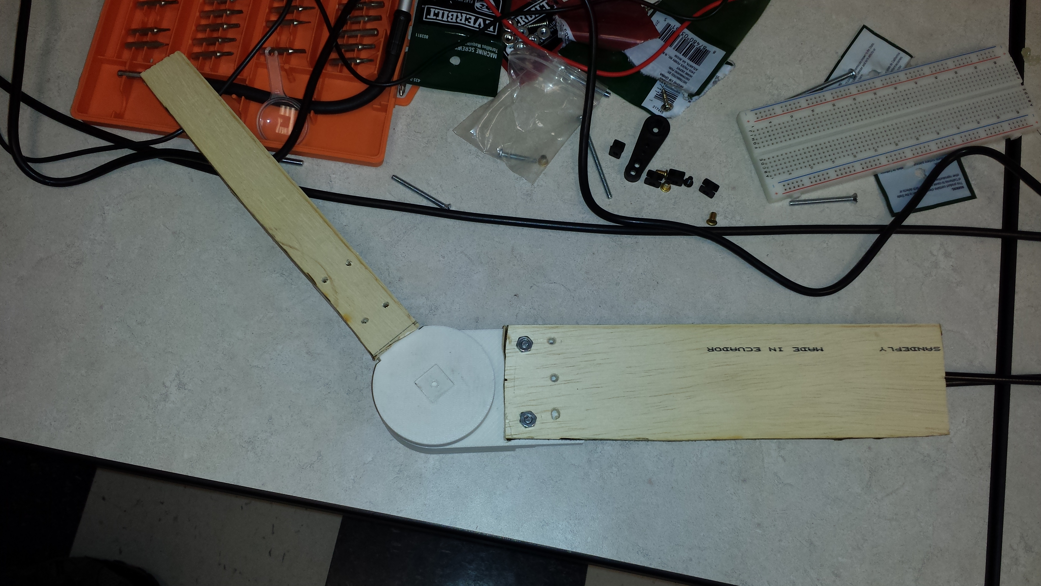
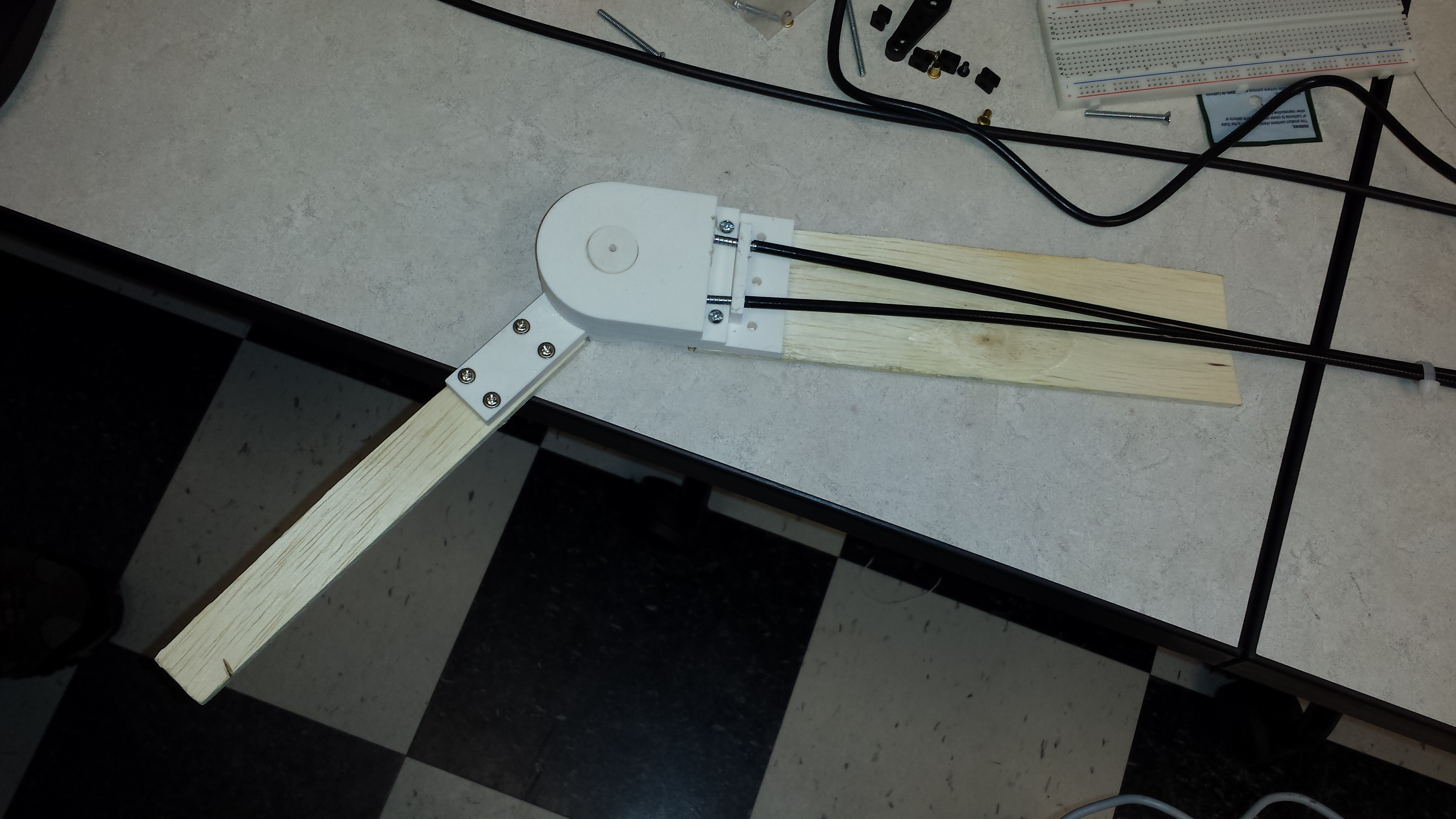
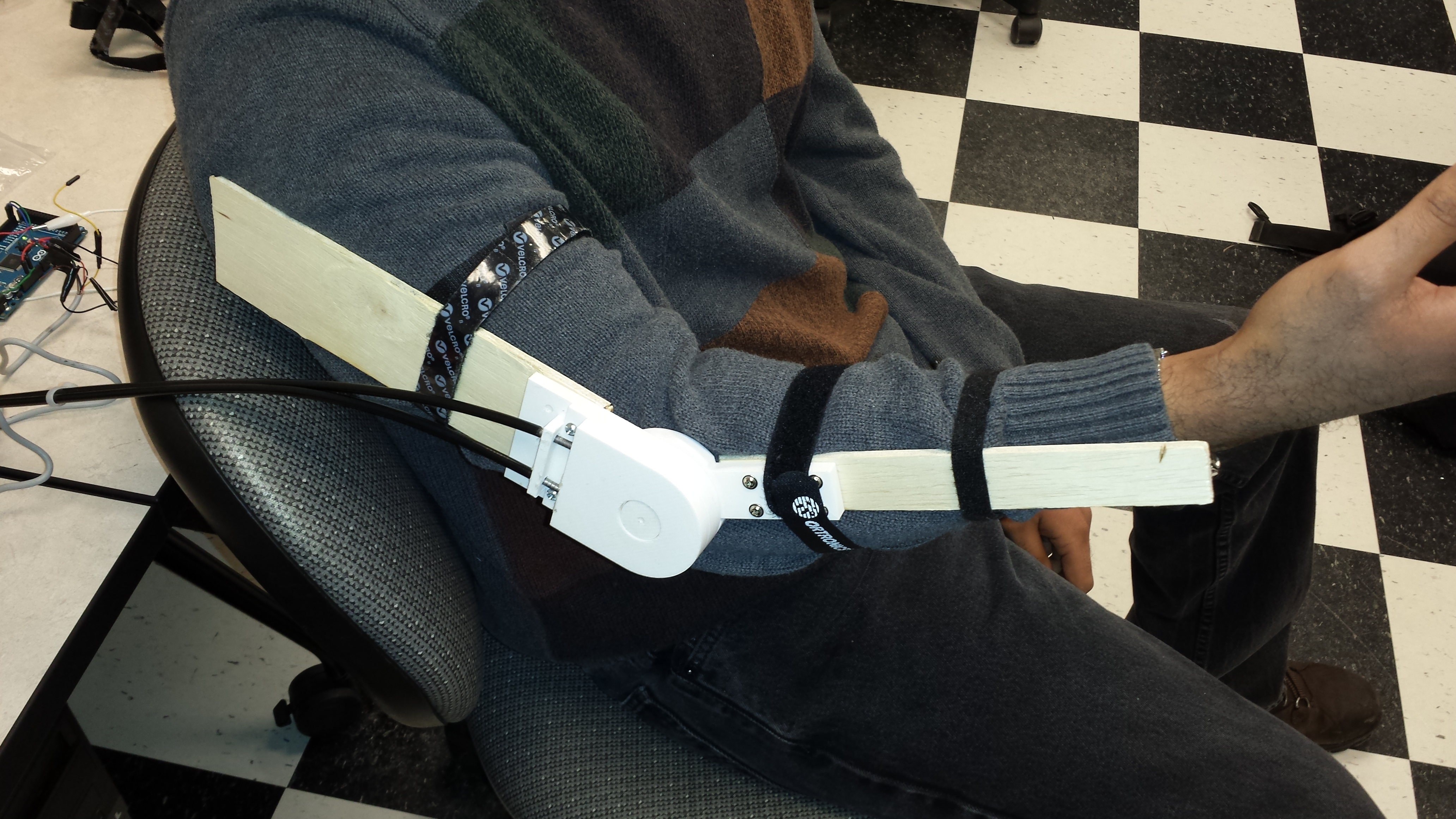
The Velcro straps were used to hold exoskeleton prototype with the arm. However, after performing this test, the arm barely had any movement, the design needs to be changed in a way that the servo is able to exert maximum torque to the arm.
3 comments
Can you explain what you mean by “after this, the arm barely had any movement”?
Good progress here. Did you test the motor with load? (several different loads?)
I’d like to see some results of speed and precision (maybe not, I don’t know) under load.
Author
After the exoskeleton was placed on the arm, we used the joystick configuration to see if the exoskeleton could move the arm. Unfortunately, using the joystick to attempt to move the arm up, there was no success. The arm barely budged, which means there’s very little torque being transferred to the arm.
The motor was not yet tested under a load, unless you consider the arm with the exoskeleton joint.
That will be one of our future tests regarding the motor.
Also, we received the flexiforce pressure sensor – 100lbs: https://www.sparkfun.com/products/8685
I was going to do some testing with that soon to see how weight relates to conductance, according to the manufacturer the conductance to weight ratio is linear. The flexiforce pressure can be made into a 1000lb force sensor through an excitation circuit shown on the manufacturer webpage. Therefore, I was thinking maybe it could be placed in a glove or in the shoe of the user.
thanks-N