
EMG Signal acquisition circuit and PCB Design
Download – PCB Design
The circuit soldered onto a Vector Board. 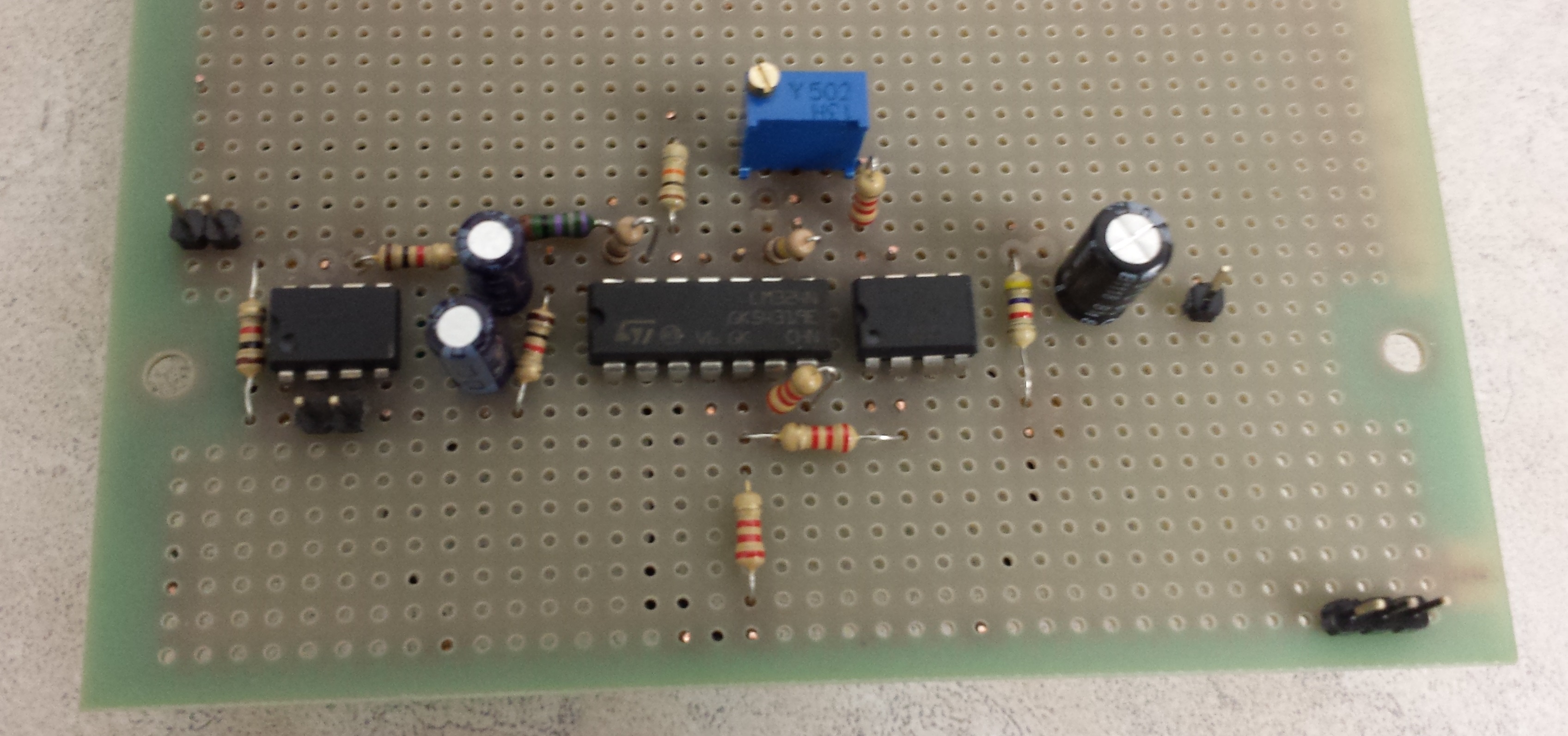 The PCB design was done through KiCAD, with the 3D simulated image shown below.
 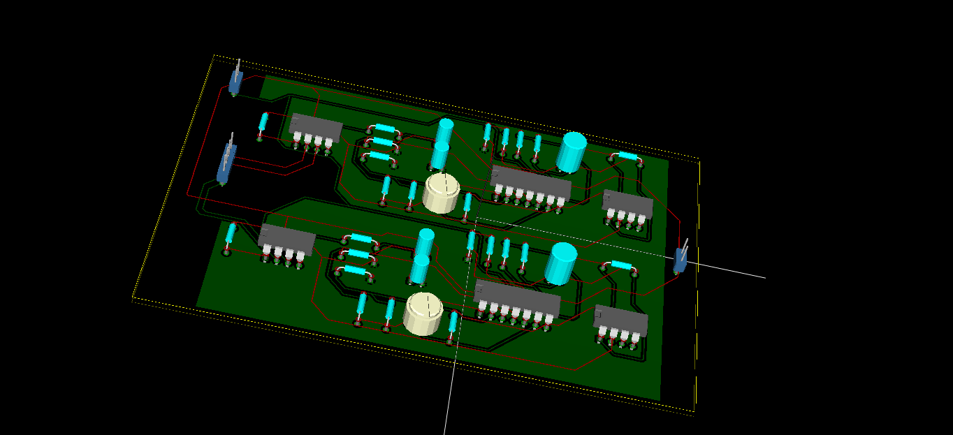 The actual PCB that came from PCB milling machine (front and back images) are shown below.
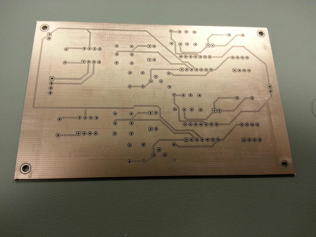
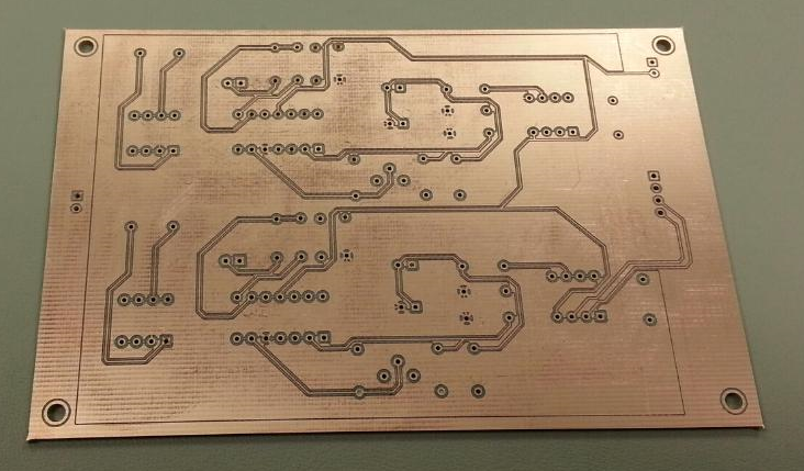 After the PCB came out, rubbing alcohol was used to remove any excess residue. We have already begun to solder the components onto the board and expect the board to be finished by this weekend. The sEMG circuit is used for the bicep and tricep muscles located on the upper arm.
1 comment
Thank you for sharing all the steps to do this in details. Appreciate the sharing.