
Apr 14
Final Report
Apr 06
Automated (EMG) Mode for the Exoskeleton Arm Brace
Exoskeleton Arm Brace controlled by Automated (EMG) Mode and Joystick Mode
In automated mode, the user’s bicep and tricep muscles control the direction of the exoskeleton arm brace. The benefit of this, is that the user will not have to rely on the joystick device to tell which direction the arm is moving. However, due to potential problems and to avoid disastrous situations, the joystick mode was also implemented. Therefore, when the button “Z” is pressed on the joystick device, the mode will change depending on the user’s preference.
After being able to successfully control the exoskeleton arm brace with EMG signals, a strength test was performed in the automated mode. The different strength tests are shown below.
Automated (EMG) Strength Test (0-3.63Kg) with Exoskeleton Arm Brace
Automated (EMG) Strength Test (2.23Kg) with Exoskeleton Arm Brace
Automated (EMG) Strength Test (3.63Kg) with Exoskeleton Arm Brace
The results showed that the arm was able to withstand the arm’s weight, with an additional 3.63Kg. The potential problems that could arise from wearing this device, is that when the arm is going down in automated (EMG) mode, a small amount of force against the exoskeleton brace is necessary for the device to understand the correct direction.
These videos were made as we were integrating our current system(controlled manually with the joystick) and the EMG circuit. The user(Rahul) was asked if the exoskeleton was supporting his arm because the exoskeleton should keep the arm in place if the amplitude of the EMG signal is below the set threshold (relatively relaxed), to which he answered yes. The initial movement before the exoskeleton kicks in is due to the fact that the steel wires were not properly tensioned(a little loose) and there was room for the arm to move, which shouldn’t happen. The idea is that the arm should be held in place unless the servo rotates. We are currently in the process of tweaking the system to get desired and more consistent results.
Apr 06
Updates to the site
Recent Updates to the Site:
–Mechanics
–User Interface
–Circuit Design
–Project Summary
Apr 06
User Interface
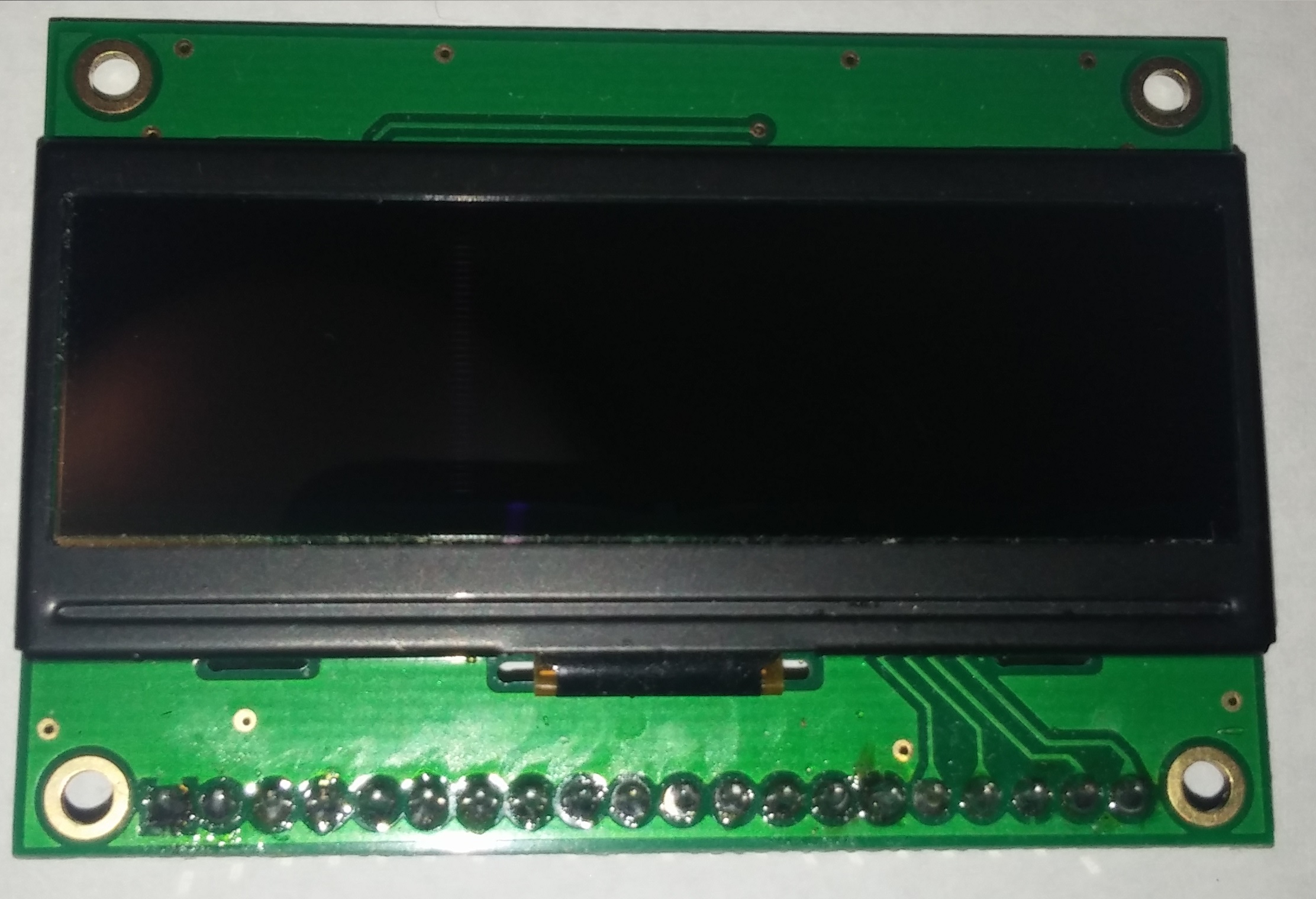
The user interface consists of an OLED display located on the forearm part of the brace. This will be used to display battery level, feedback messages, and warnings. If we can, we will place a couple of buttons to select options in the OLED display. Otherwise, the joystick will be used to make said selections.
In addition a low battery level warning device which came with the LiPo battery will be placed in the backpack. This device has a powerful buzzer which will beep when any of the four battery cell voltages approaches low voltages. This is necessary because the battery will get damaged if the cell voltages go below the minimum specifications.
Mar 27
Strength Test (3 Trials) with Updated Exoskeleton Design
The three strength test trials are shown below.
Trial #1
Trial #2
Trial #3
This test was done using the 320Kg*cm servo motor. A variety of weights up to 8 pounds were used, where the outcome of the experiment was determined through the angle shown on the brace for each weight.
Results
- Trial #1: 70 degrees for all weights
- Trial #2: 60 degrees for all weights
- Trial #3: 60 degrees for all weights
From the first trial to the second trial, the exoskeleton arm brace lost tension in the Bowden cable. This resulted in a loss of angle from 70 degrees to 60 degrees. Also, there was a systematic error with the strength test because for all the weights, the angle remained the same.
Since this failed test, we have updated the exoskeleton arm brace to not lose tension (which resulted in the correct angle desired).
Mar 25
PCB Design
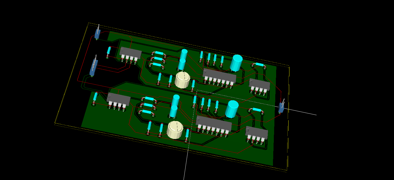
The PCB design was done through KiCAD, with the 3D simulated image shown below.
The actual PCB that came from PCB milling machine (front and back images) are shown below.
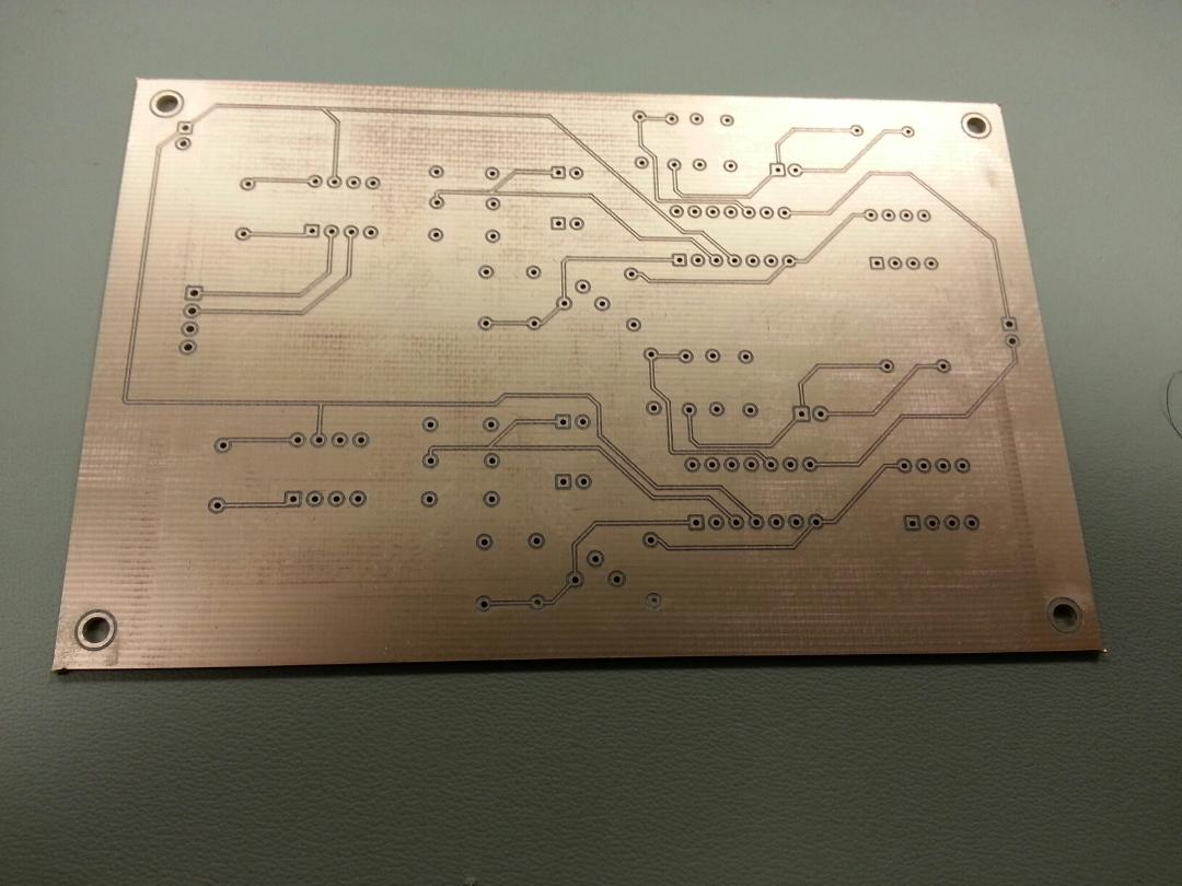
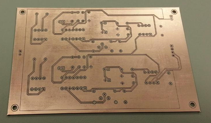
After the PCB came out, rubbing alcohol was used to remove any excess residue. We have already begun to solder the components onto the board and expect the board to be finished by this weekend. The sEMG circuit is used for the bicep and tricep muscles located on the upper arm.
Mar 21
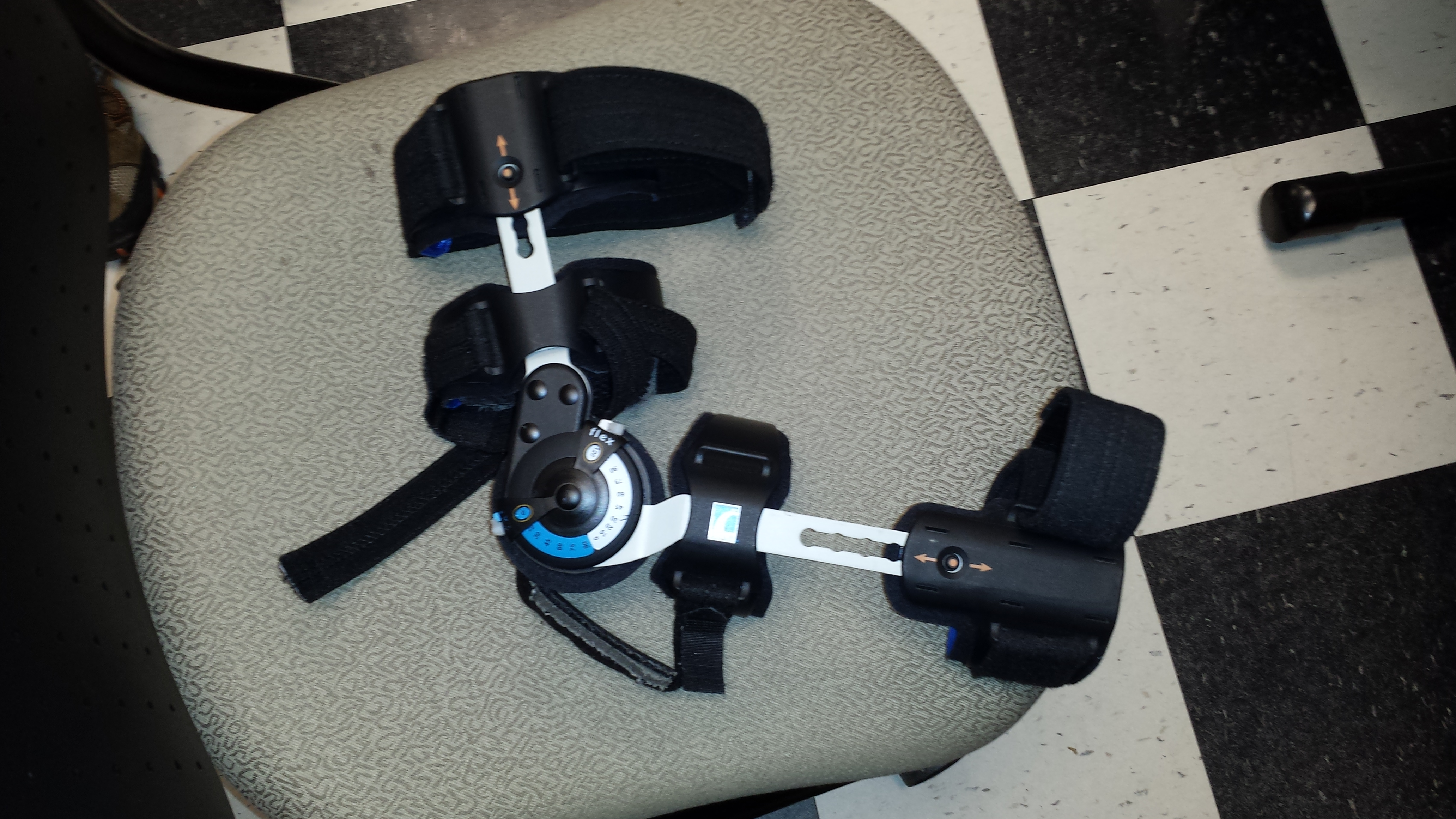
Adjustable Arm Brace, Force Sensing Resistor (100 pounds)
Through an auction on ebay, we placed a bid and won an adjustable metal arm brace that is used for rehabilitation purposes. To improve on our design, which was previously plastic, we have decided to use this arm brace to support the arm with the large amount of torque provided by the servo motor. The arm brace is shown below.
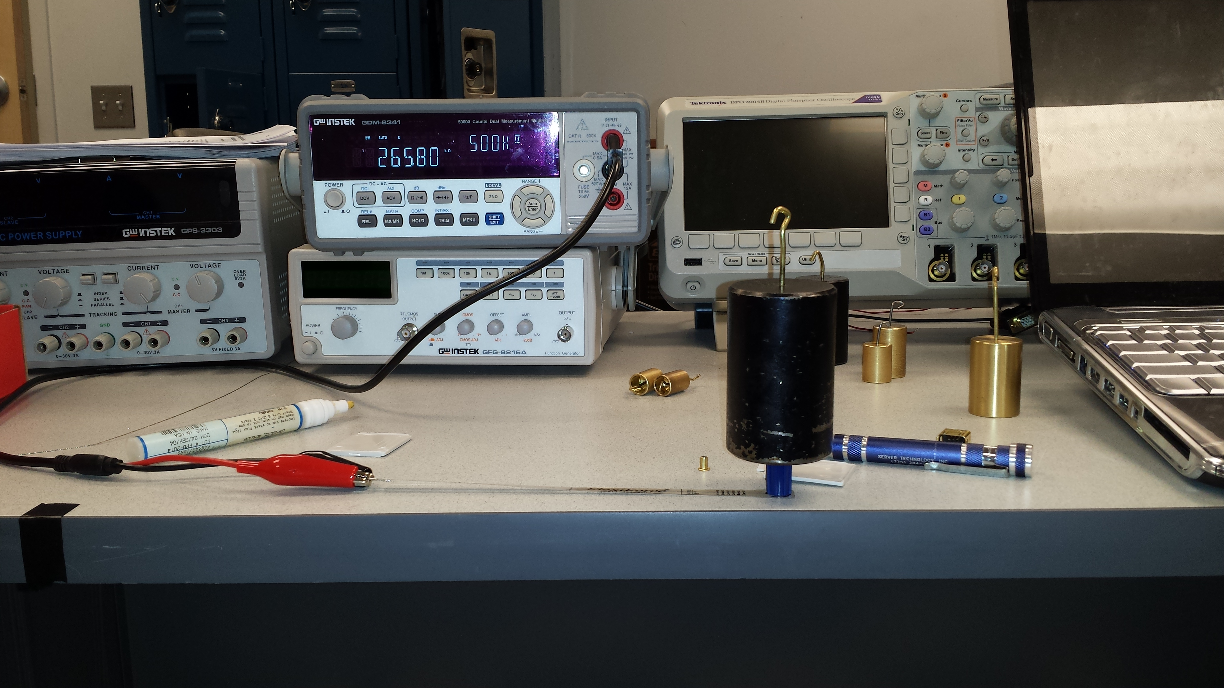
Also, we have tested the 100 pound force sensing resistor (FSR), which is shown below.
The FSR works by providing a resistance depending on the force exerted in the sensing area. This is useful to show the user how much the user is lifting through the OLED display. In order to get accurate results, numerous different weights were placed on the FSR to determine the output resistance. The manufacturer states that the weight placed on the FSR is linear with the conductance of the FSR. Since, all of the weight must be placed on the sensing area, a small object that encompassed about the same area was placed below the desired weight. An example of how the testing was done is shown below.
A table of values and graph was plotted and is shown below.
Download – FSR Data
Mar 14
Strength Test, New Servo, Power Consumption
We performed a strength test with the 40Kg*cm servo with 55rpm shown below.
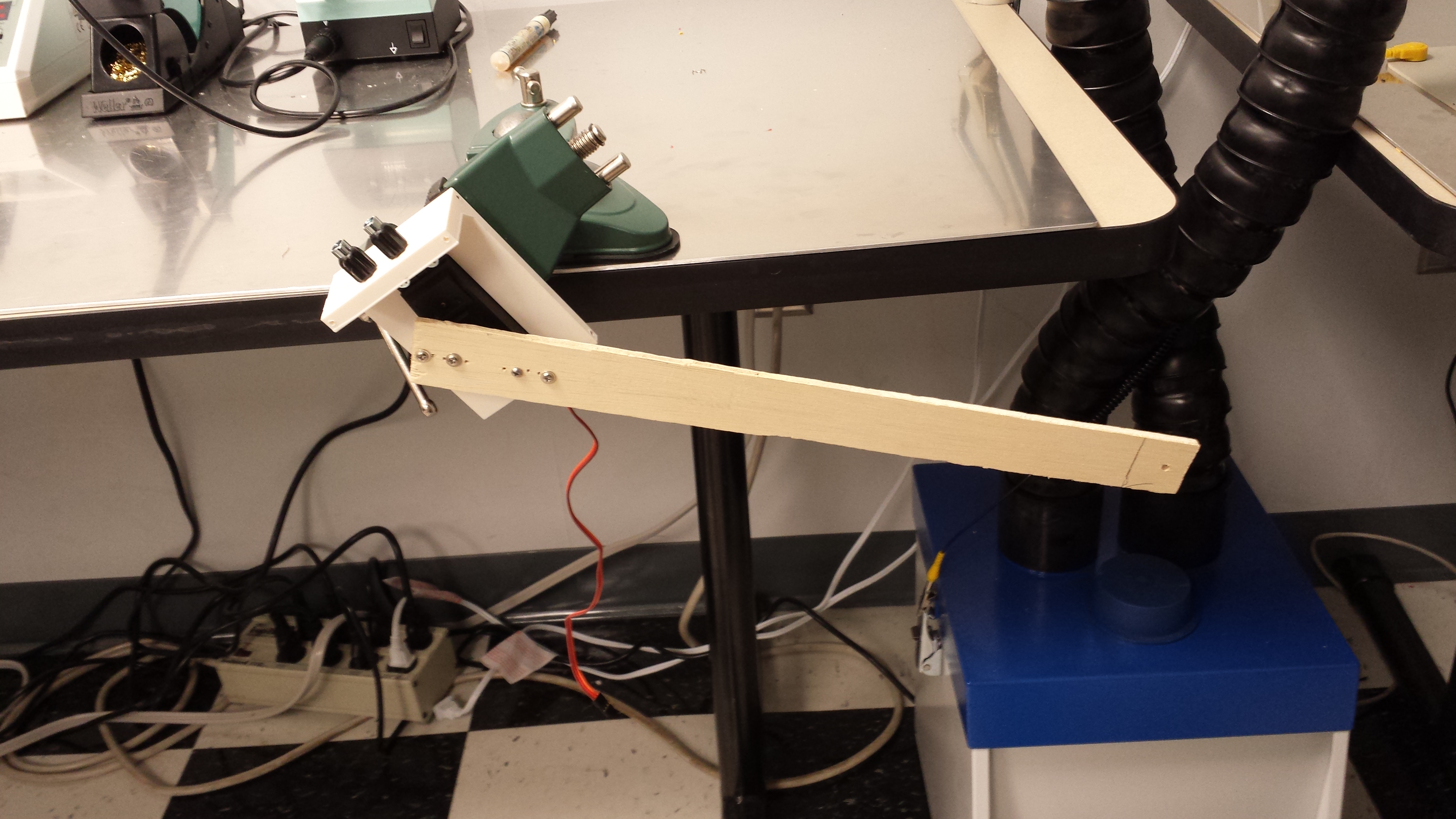
After performing the strength test, the maximum amount of weight that the servo could handle at 26cm was 2 pounds. We realized that this servo was incapable of carrying an arm, therefore we decided to upgrade our servo motor. This was a very inefficient servo, also noting the high amount of current (9A stall current) used to carry relatively small weight.
Therefore, we decided to purchase a much more powerful servo motor. The new servo motor is shown below.
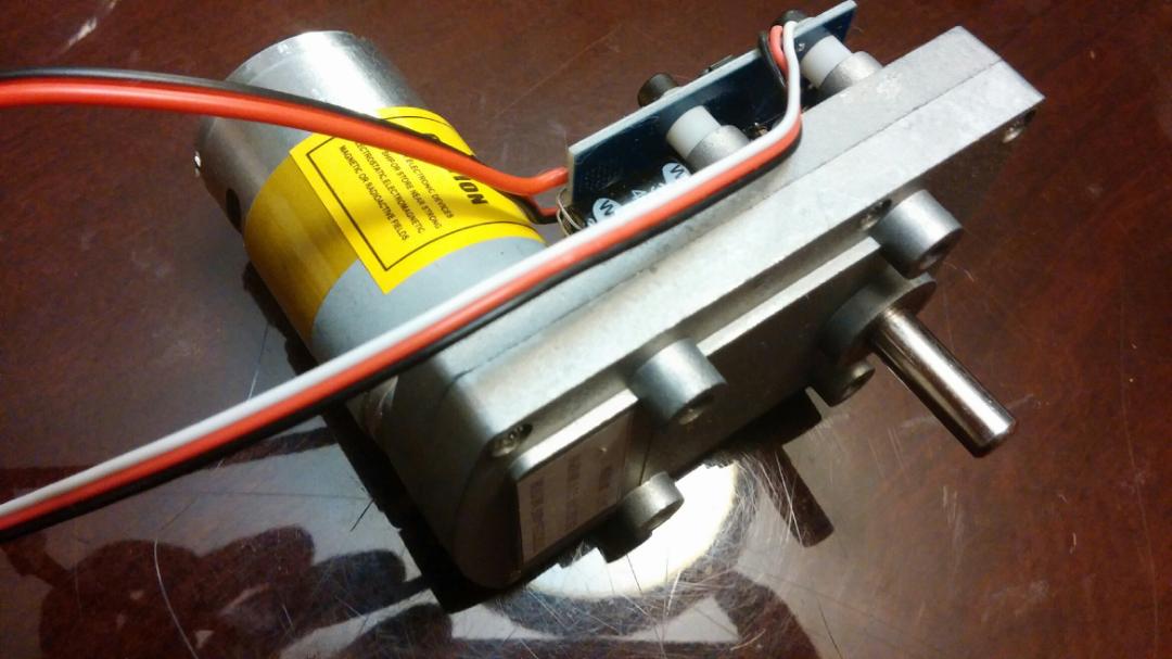
The specs for the servo are shown below:
Price: $100
Voltage: 12Vdc ~ 24Vdc
Maximum current: 6.8A
No-load current: <500mA
Max torque: 320kg.cm(24v) ; 160kg.cm(12v)
No-load speed: 46 rev / min 12V ; 92rev / min @ 24V
Rotation angle: 180 ° (can be customized)
The input signal pulse width: 0.5 ~ 2.5ms
Dead time: 4us
Weight: 530g
Gear Material: Steel
Dimensions: 95.5mm X 60.5mm X 102.6mm
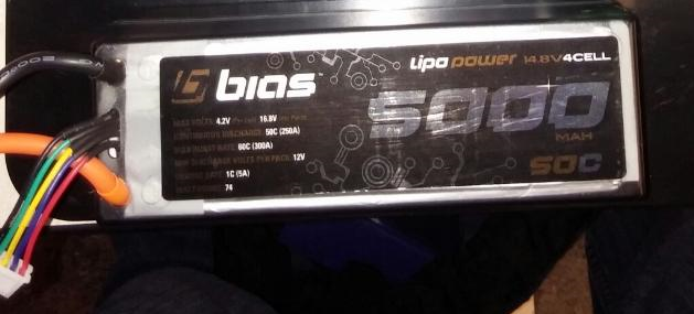
As compared to the previous servo, this servo is much more efficient in terms for current usage and the amount of torque it can produce. Through this information, we purchased a 14.8V – 5AH lithium polymer battery and charger to use with this servo. The battery is shown below.
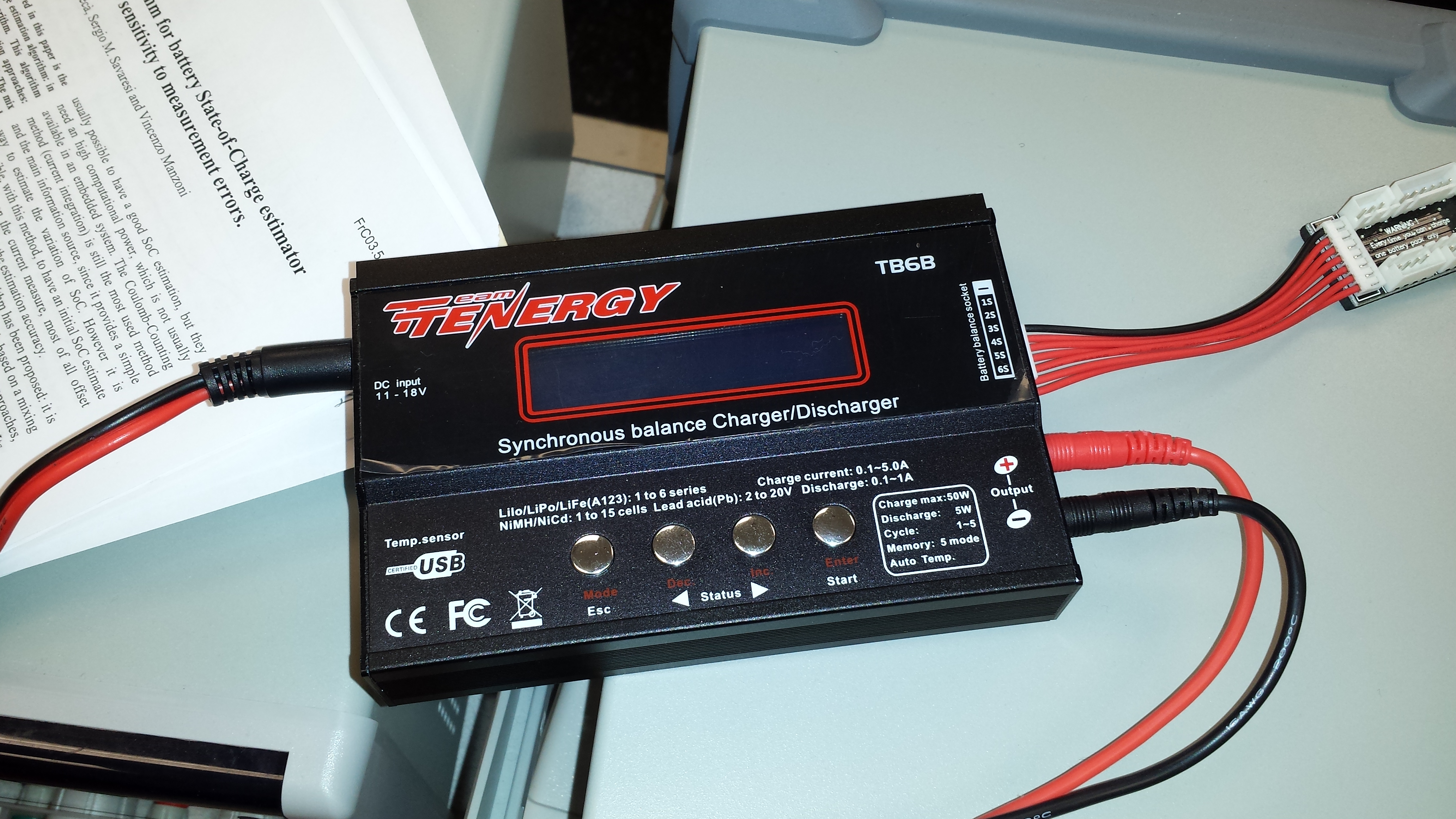
The charger is shown below.
In order to produce the maximum torque allowed on the servo, we purchased a 600W boost converter. The converter is shown below.
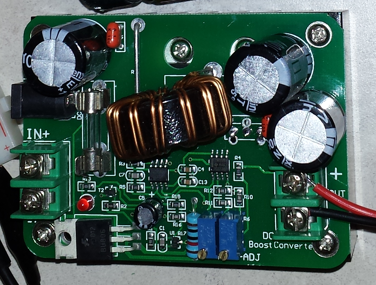
This converter allows us to convert the 14.8V to 24V. In order to provide a higher voltage, the input current must be increased. Therefore to satisfy this servo’s maximum current (6.8A) the equation is as follows:
P1 = P2
P1 = VI
P1 = (24V)*(6.8A)
P1 = 163.2W
163.2W = (14.8V)*I
I = (163.2W)/(14.8V)
I = 11.027A
Therefore, the maximum current that the battery will use at any given point from the servo is 11.027A. Although, the power usage is much higher than the previous servo, the amount of weight it can handle is much higher.
The average forearm length is 26cm and the servo can handle a maximum of 320Kgcm, therefore since:
Torque = F*d
320Kg*cm = F*26cm
F = (320Kg*cm)/(26cm)
F = 12.3Kg * 9.81 m/s^2
F = 120.663N
Or in otherwords, the servo can carry up to 12.3Kg (27 pounds) at a forearm’s length of 26cm.
Also, we purchased relays to switch on/off the power, controlled through the microcontroller. The relays are shown below.
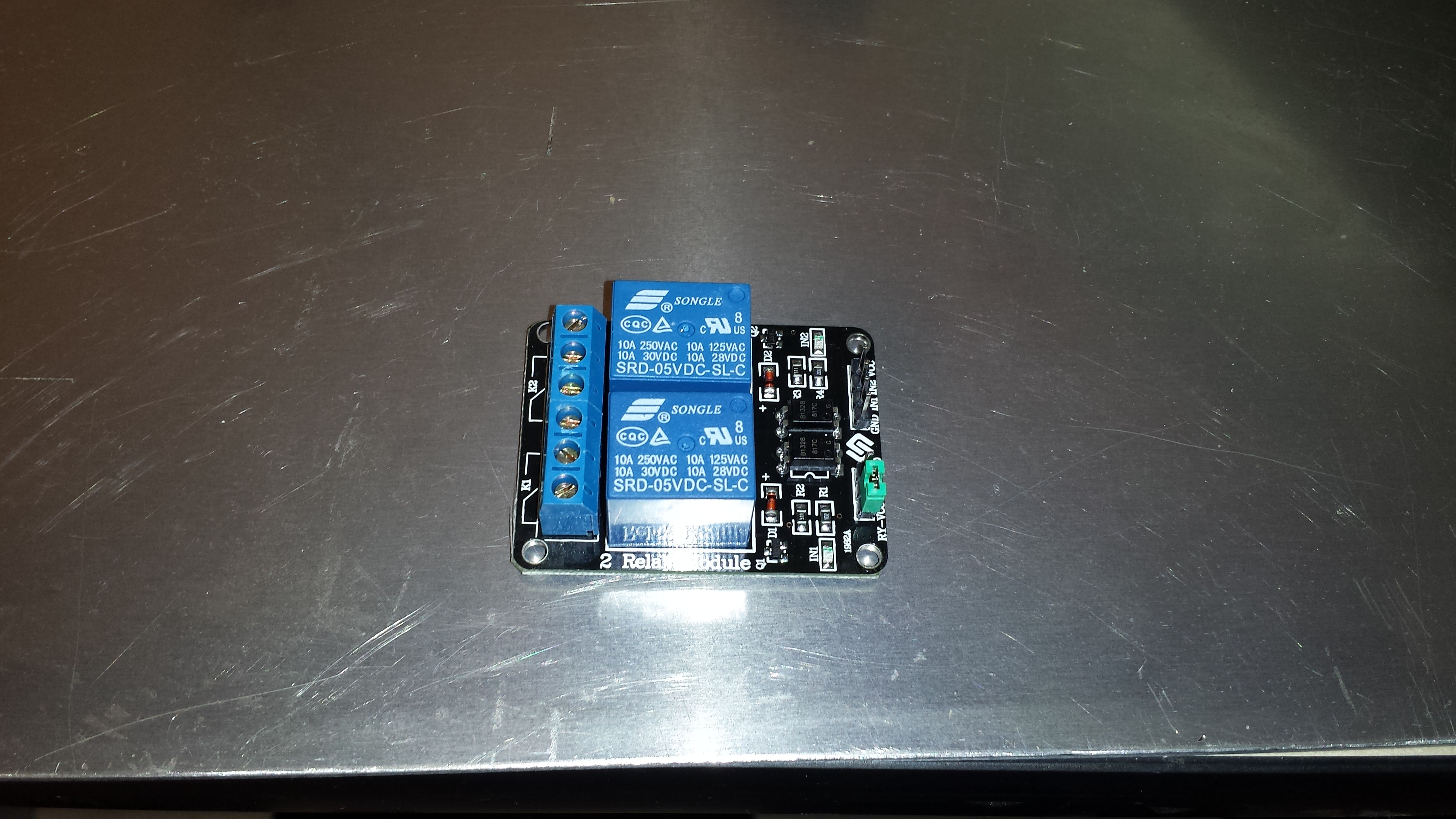
- 1
- 2
Recent Comments